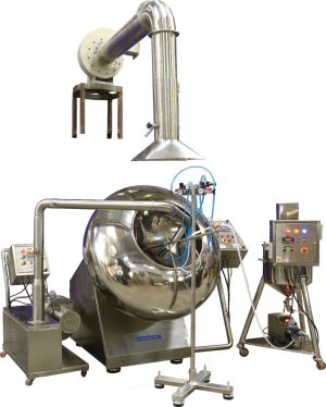
MODEL: 12″ /18” / 24” / 36” / 48” / 60″
Salient Features:
- Perforated pan with drive and mounting facility in the chamber. Chamber with wash water drain port and manually operated ball valve.
- Motor with worm reduction gear unit and bearing housing, along with Variable Frequency Drive for variable speed control.
- Inlet and exhaust air duct with butterfly valve and pneumatic actuator.
- Flameproof (FLP) lamp at the top of the chamber.
- Mounting facility for spray nozzles.
- Perforated pan made from 10 SWG SS316 material, polished to a mirror finish with baffles and tablet unloading attachment.
- Air Handling Unit (AHU) with pre-filters, inlet air blower, cooling coil, phase and bypass system, heating coil, micro V and HEPA filters, temperature sensor, RH sensor, and exhaust air blower.
- Inlet and outlet air ducts.
- Exhaust air blower.
- Solution preparation vessel with spraying system.
- Pan fabricated from 2.5mm thick SS316 sheet with 3.0mm perforation at 4.5mm triangle pitch.
- Models sized 12” and 24” are on wheels, while 36”, 48”, and 60” models feature an anti-vibrating unit for proper leveling without needing a foundation.
- Double-wall PUF insulated AHU with aluminum framing, pre-filters, micro V filters, HEPA filter, cooling coil, phase and bypass damper, heating coil, and optional steam or electric heating.
- RH sensor at the air inlet line, differential pressure gauges at the HEPA filter and process chamber, and temperature sensors for inlet air, product bed, and exhaust air.
- Variable Frequency Drives for pan drive motor, inlet air blower, and exhaust air blower.
- Pan RPM indication facility, FLP lamp, port with spray ball for CIP, inlet and exhaust air blowers, solution preparation vessel with stirrer, flameproof pan drive motor, spraying nozzles, peristaltic pump, and manually operated pressure regulators.
- Butterfly valves at inlet and exhaust air ducts with actuators.
- PLC-based power panel with touch screen-based operating panel.
Optional / Additional Features:
- Pan made out of SS 316 or SS 316 L Material instead of SS 304 Material
- Panmade out of SS316 or SS316 L material instead of SS304 material.
- Dew Point Sensor at inlet air duct. instead of Rh sensor.
- Velocity Trans-meter at inlet & exhaust air duct.
- Differential pressure Trans-meter at AHU &Process Chamber, instead of Differential pressure gauge.
- Jacketed Vessel instead of non jacketed. (for Solution Preparation.).
- Flameproof Model Vessel for Solution Preparation.
- Flameproof Motor for inlet air & Exhaust air blower.
- Wet Scrubber at exhaust air.
- Steam & Chilled Water Controlling Valve.
- Peristaltic Pump of Master Flex-USA make instead of Indian make.
- Spray nozzle of “Spraying System – U.S.A.” make instead of Indian make.
- Flow Meter at Solution Spray System. ( Emersion make ( USA) – Coriolis Type. )
- Atomizing Air Pressure Regulator & Fan Width Pressure Regulator operating through Operating Touch Screen.
- Flameproof / Weatherproof Enclosure for Touch Screen.
- Additional Duct per 1 Meter – Non insulated / Insulated. ( for Inlet air line &Exhaust air line).
- Tablet discharge spout.
- Additional Pan.
- Pan unloading trolley.
Technical Specification:
| Sr. No. |
Description |
Size : 12″ |
Size : 24″ |
Size : 36″ |
Size : 48″ |
Size : 60″ |
| 1 |
L |
1200 MM |
1200 MM |
1730 MM |
1975 MM |
2650 MM |
| 2 |
L1 |
1500 MM |
1500 MM |
2030 MM |
2275 MM |
2950 MM |
| 3 |
H |
1500 MM |
1535 MM |
1540 MM |
2120 MM |
2650 MM |
| 4 |
H1 |
1850 MM |
1885 MM |
2290 MM |
2470 MM |
3000 MM |
| 5 |
W |
840 MM |
955 MM |
1480 MM |
1600 MM |
2100 MM |
| 6 |
W1 |
2180 MM |
2585 MM |
3780 MM |
4380 MM |
5400 MM |
| 7 |
PAN MOTOR HP |
0.5 HP. |
1 HP. |
2 HP. |
3 HP. |
7.5 HP. |
| 8 |
INLET BLOWER MOTOR HP |
0.5 HP. |
1.5 HP. |
3 HP. |
5 HP. |
7.5 HP. |
| 9 |
EXHAUST BLOWER MOTOR HP |
1 HP. |
2 HP. |
5 HP. |
7.5 HP. |
15 HP. |
| 10 |
PERISTALTIC PUMP MOTOR HP. |
0.5 HP. |
0.5 HP. |
0.5 HP. |
0.5 HP. |
0.5 HP. |
| 11 |
HEATER K.W. / STEAM Kg./Hrs. |
12 K.W. / 30 Kg |
12 K.W. / 30 Kg |
36 K.W. / 75 Kg |
60 K.W. / 150 Kg |
Not. App. / 250 Kg |
| 12 |
PAN RPM |
5 to 25 |
5 to 25 |
5 to 25 |
5 to 25 |
5 to 25 |
| 13 |
INLET AIR CFM |
100 CFM |
250 CFM |
1200 CFM |
2500 CFM |
5500 CFM |
| 14 |
EXHAUST AIR CFM |
150 CFM |
450 CFM |
1400 CFM |
3000 CFM |
6000 CFM |
| 15 |
NOS. OF NOZZLE |
1 No. |
1 No. |
2 No. |
3 No. |
4 No. |
| 16 |
SOLUTION PREPARATION TANK |
15 Ltr |
25 Ltr |
50 Ltr |
100 Ltr |
150 Ltr |
| 17 |
AIR AT 5 Kg./ CM2 CFM |
20 CFM |
25 CFM |
35 CFM |
45 CFM |
60 CFM |
* Depending upon the tooling size, shape and material characteristics
Note: We reserve right to change specifications without any prior notice.
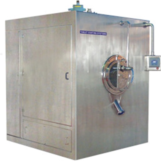
Tablet Coating System – Automatic R & D MODEL
MODEL: 12″ TO 18″

Salient Features:
- Pan fabricated from 3.0mm thick SS316 sheet with 3.0mm perforations at 4.5mm triangle pitch.
- Lab model machines are on wheels, eliminating the need for a foundation.
- Air Handling Unit (AHU) with SS sheeting inside, including pre-filters, micro V & HEPA filters in SS boxes, cooling coil in copper tube and aluminum fins, and heating coil in SS tube & aluminum fins.
- RH sensor at the air inlet line, differential pressure gauges at HEPA filter and process chamber, and temperature sensors for inlet air, product bed, and exhaust air.
- Variable Frequency Drives for pan drive motor, inlet air blower, and exhaust air blower, with RPM indication facility.
- Flameproof (FLP) lamp, port with spray ball for WIP (Washing in Place), tablet discharge spout, inlet air blower, and exhaust air blower.
- Solution preparation vessel with stirrer (plain, non-jacketed, non-FLP model).
- Flameproof pan drive motor, spraying nozzle, peristaltic pump, and manually operated atomizing air pressure regulator & fan width pressure regulator.
- Butterfly valve at inlet and exhaust air ducts with actuator.
- PLC and touch screen for operation.
- Inlet and exhaust air ducts.
Optional / Additional Features:
- Dew Point Sensor at inlet air duct, instead of Rh sensor.
- Velocity Trans-meter at inlet & exhaust air duct.
- Differential Trans-meter at AHU & Process Chamber, instead of D.P.G. (02 nos.)
- Jacketed Vessel instead of plain. (for Solution Preparation.).
- Flameproof Model Vessel for Solution Preparation.
- Flameproof Motor at inlet & Exhaust air blower.
- Wet Scrubber at exhaust air.
- Steam & Chilled Water Controlling Valve. (02 nos.)
- Atomizing Air Pressure Regulator & Fan Width Pressure Regulator operating through Touch Screen.
- Flameproof/Weatherproof Enclosure for Touch Screen.
- Additional Duct per 1 Meter – Non- insulated.
Technical Specification:
| Sr. No. |
Description |
Size : 12″ |
Size : 15″ / 18″ |
| 1 |
L |
1140 MM |
1200 MM |
| 2 |
L1 |
1260 MM |
1500 MM |
| 3 |
H |
1465 MM |
1535 MM |
| 4 |
H1 |
1765 MM |
1885 MM |
| 5 |
W |
630 MM |
955 MM |
| 6 |
W1 |
1610 MM |
2585 MM |
| 7 |
PAN MOTOR HP |
0.5 HP. |
1 HP. |
| 8 |
INLET BLOWER MOTOR HP |
1 HP. |
1.5 HP. |
| 9 |
EXHAUST BLOWER MOTOR HP |
1 HP. |
2 HP. |
| 10 |
PERISTALTIC PUMP MOTOR HP. |
0.5 HP. |
0.5 HP. |
| 11 |
HEATER K.W. / STEAM Kg./Hrs. |
12 K.W. |
12 K.W. |
| 12 |
PAN RPM |
5 to 30 |
5 to 25 |
| 13 |
INLET AIR CFM |
100 CFM |
250 CFM |
| 14 |
EXHAUST AIR CFM |
150 CFM |
450 CFM |
| 15 |
NOS. OF NOZZLE |
1 No. |
1 No. |
| 16 |
SOLUTION PREPARATION TANK |
15 Ltr |
25 Ltr |
| 17 |
AIR AT 5 Kg./ CM2 CFM |
20 CFM |
25 CFM |
* Depending upon the tooling size, shape and material characteristics
Note: We reserve right to change specifications without any prior notice.